FREQUENTLY ASKED QUESTIONS:
Q: What type of fuel is best?
A: There are many advantages and disadvantages to different types of fuel. Nearly all Generators use gasoline, diesel, natural gas, or propane. The following information will hopefully answer any questions or concerns you may have concerning different fuel sources.
Gazoline:
- Advantages:
- Common fuel source – easily obtained
- Increases portability of smaller generators
- Disadvantages:
- Highly flammable
- Short shelf life (approximately 12 months)
- Storing large quantities is hazardous
- May not be available during power outages
- Somewhat Expensive ($1.50 to $2.00 per Gallon)
- Inefficient
Propane:
- Advantages:
- Long shelf life
- Clean burning
- Easily stored in both large tanks or in smaller 5 – 10 gallon cylinders
- Obtainable during power outages – gas stations may be unable to pump fuel during an area wide outage
- Home delivery available for larger tanks
- Disadvantages:
- Pressurized cylinder of flammable gas
- Fuel system is more complicated (increased possibility of failure)
- Larger tanks are not aesthetically pleasing (unsightly)
- Fuel system plumbing results in higher installation cost
- Somewhat Expensive ($1.60 to $1.80 a gallon)
Natural Gas:
- Advantages:
- Unlimited fuel source – refuelling not necessary
- Clean burning
- Available during power outages
- Disadvantages:
- May be unavailable during natural disasters (earthquakes, etc)
- Lower power output (30% less BTU’s per unit than gasoline)
- Fuel system plumbing results in higher installation cost
- Not available in many areas
Diesel:
- Advantages:
- Least flammable fuel source
- Easily obtained
- On-site fuel delivery available
- Disadvantages:
- 18-24 month shelf life
- Installing large storage tanks raises the cost of the system
- May not be available during power outages
Q: What size generator do I need?
A: Power requirements must be determined to properly size your generator. We are providing some steps to assist you in approximating the size generator for your power needs. Please keep in mind that unless you are qualified, you should use a certified electrician to determine your power needs. At Americas Generators it is our goal to assist our customers in any way possible. If you have any questions, please do not hesitate to contact us.
STEPS TO DETERMINE GENERATOR REQUIREMENTS
Determine your need. Do you want the generator to operate part or all of your home or office?
Identify the appliances and/or tools the generator will need to power.
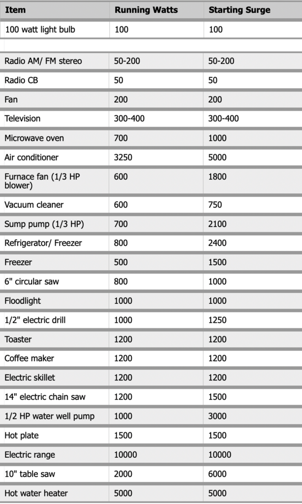
Determine the wattage for each appliance and tool you plan to use frequently. The “Common Wattage Guide” below will help you determine your need.
Total the wattage for appliances and tools you frequently use.
Identify motor and pump requirements. Use the motor and pump charts provided below.
Calculate and total the wattage for the motors and pumps frequently used. Always use starting watts, not running watts, when determining the correct electrical load requirements.
Total the wattage of the appliances & tools and the motors & pumps.
Keep in mind that if you coordinate your power usage wisely you do not have to operate everything all at once. Therefore, for emergency use you don’t necessarily need to size the generator to operate everything simultaneously.
Convert watts into kilowatts by dividing the watts in step VI. to determine the generator size required. Please note that it is suggested, although not absolutely necessary, to size the generator 20-25% over the size you determine your needs to be. This will allow room for future growth. For example, if you determine that you will need a 15 kW generator then it is advisable to purchase an 18 kW generator to accommodate future expansion.
Common Wattages
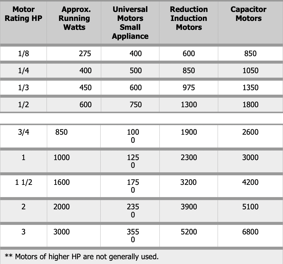
Electric Motor Wattage Requirements
Electrical motors present special electrical startup considerations. They can require up to three times their rated running wattage to start. Motor nameplates generally will show starting watts, some as high as nine times the running wattage. Check the nameplate to be sure. Be certain to use the starting watts when figuring the correct electrical load requirements. Motor load requirements are listed below:
Water Well Pump KW Requirements
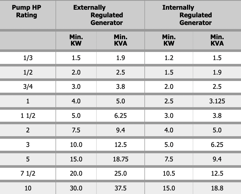
NOTES: 1. It is recommended that the generator be started before the pump motor is turned on.
- A majority of industrial generators are externally regulated. Generators must be sized to deliver at least 65% of the rated voltage during motor starting to ensure adequate motor starting torque.
- Industrial generators typically produce 300+ percent of rated capacity for 15- 20 seconds during electrical surges.
- To convert KW into watts multiply KW (x) 1000.
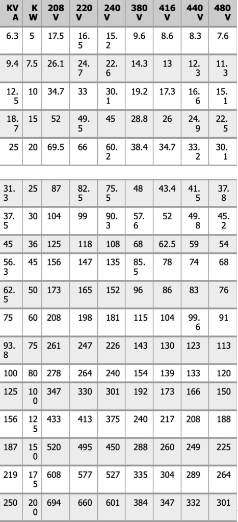
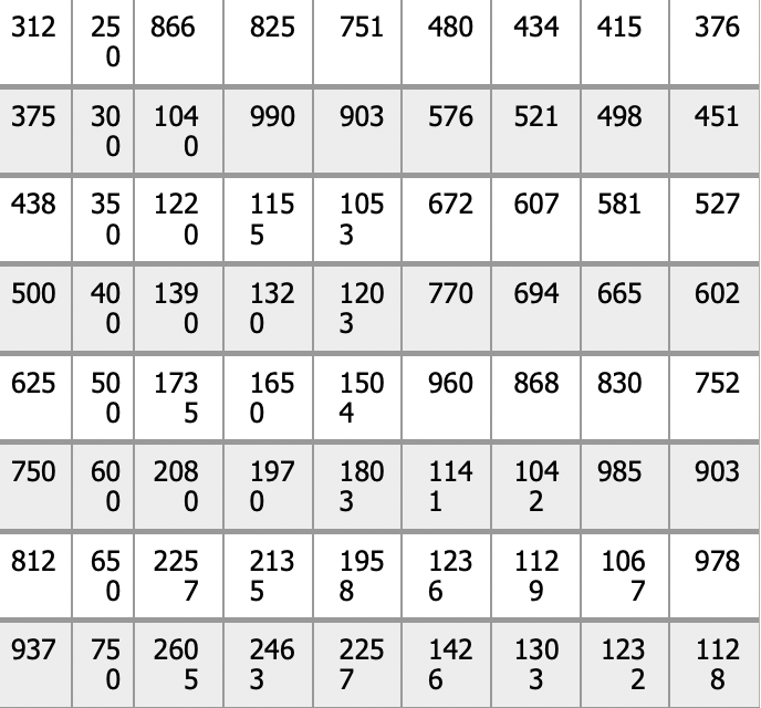
Q: How do I convert AMPS to kW or KVA?
A: Use the following conversion charts:
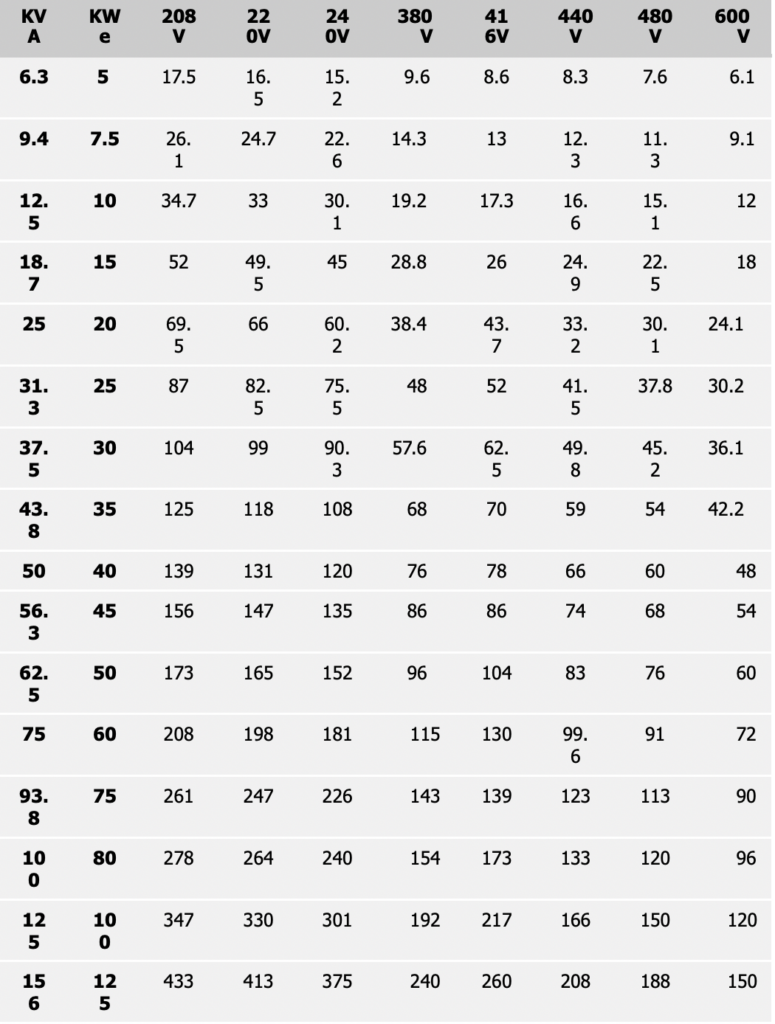
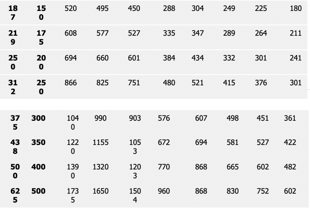
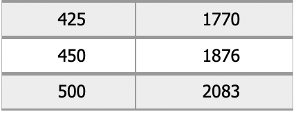
3 PHASE AMPERES – 80% POWER FACTOR
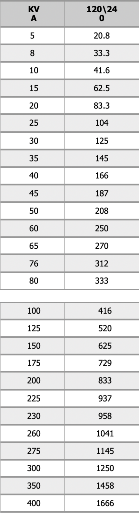
SINGLE PHASE AMPERES
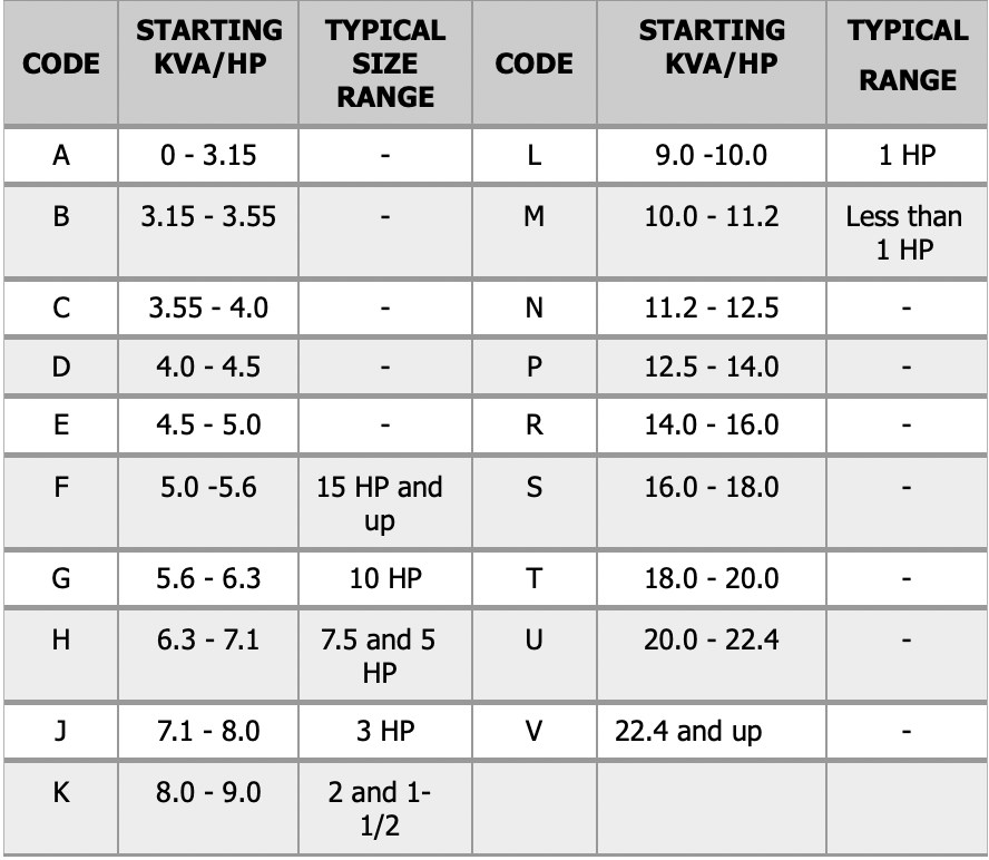
NEMA Codes for Starting KVA/hp Three Phase Motors
Q: How do I apply generator sets to motor loads?
A: Applying Generator Sets to Motor Loads. By Robert A. Barr, Product Specialist, Kohler Co., Generator Division © 1983 by KOHLER CO.
Motor starting is one of the major applications of both prime power and standby generator sets.
Years of experience in successfully applying generator sets to motor loads leads us to the conclusion that the subject is often complicated beyond necessity.
The basic characteristic of motor loads that causes difficulty is that motors draw high starting currents when started at full voltage. A typical motor, if there is such a thing, draws approximately six times its rated full load current when starting, and continues to do so with only a slight reduction until it reaches about 75% of rated speed.
Figure 1: Starting vs Running Loads
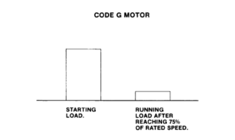
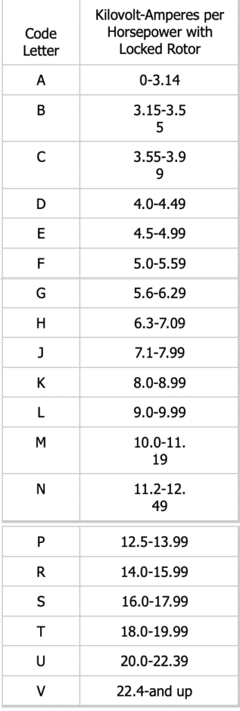
Table 1: Locked-Rotor Indicating Code Letters
The KVA required by a motor starting at full voltage is quite close to the “locked rotor KVA” requirement of the motor, which is usually fairly easily determined either from the actual motor’s nameplate or from the manufacturer. The National Electrical Manufacturer’s Association (NEMA) sets design standards for motors, and has established a NEMA Code letter designation to classify motors by the ratio of locked rotor KVA per horsepower. These code letters range from A to V, covering motors with a locked rotor KVA per horsepower of
3.14 or less to 22.4 KVA per horsepower or more. Small motors commonly have a higher NEMA Code letter and corresponding higher locked rotor KVA per horsepower requirement than large motors. Typical motor sizes and codes are:
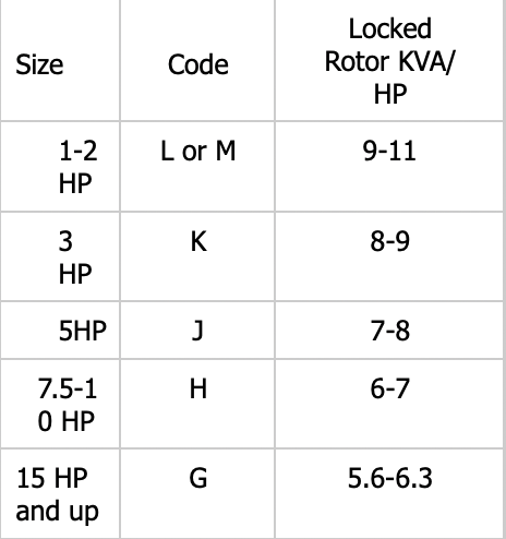
Table 2: Typical Code Letters for Various HP Motors
Fractional horsepower motors usually have even higher locked rotor KVA requirements. In trying to identify motors, the NEMA Code letter should not be confused with the NEMA Design letter which refers to the motor’s torque curve.
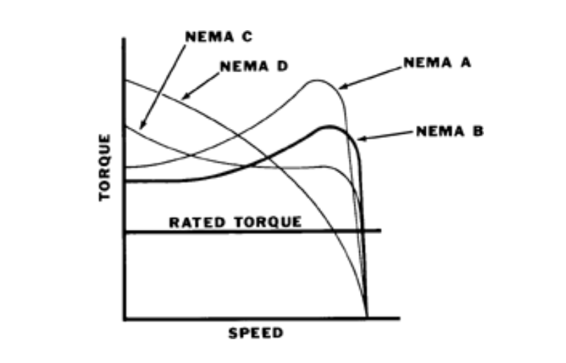
Figure 2: National Electrical Manufacturer’s Association Motor Design Code
Since the KVA requirements of a motor running at full load and rated speed are normally somewhat less than one KVA per horsepower except for small motors, it would obviously be very inefficient to size a generator set by matching its rated continuous or standby KVA to the motor’s locked rotor or starting KVA rating. Several factors combine to make this conservative approach unnecessary.
One of these is the power factor. Three-phase generator sets are usually rated in KVA at 0.8 power factor. The actual power factor of a given motor load during starting is difficult, if not impossible to measure since it is changing constantly. Various sources put it in the range of 0.3 to 0.5. A typical generator set will produce somewhere near twice its continuous rated KVA at 0.4 Power Factor for the time required to accelerate a motor to the speed at which its KVA requirement drops sharply. The engine does not stall even though the generator set is delivering more than rated KVA, because only slightly more horsepower is required for reduced generator efficiency on low power factor loads (see Figure 3). This generator characteristic allows us to obtain satisfactory motor starting results with generators half the size which would theoretically be required using the most conservative approach of matching the generator 0.8 Power Factor KVA rating to the motor locked rotor KVA rating.
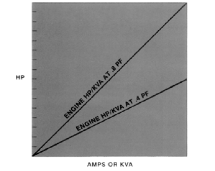
.4 Power Factor = 50% HP Factor
Figure 3: Engine Power Required for Low Power Factor Load
The other factor which can substantially reduce the size generator set needed for a particular motor load is voltage dip. Values for motor locked rotor current or KVA are based on full voltage starting. In practice, there is always some voltage dip even when starting on utility power. When voltage drops, current also is reduced proportionately so that starting KVA is reduced as the square of the voltage dip. A 30% voltage dip reduces KVA by about 50% (0.7 volts x 0.7 amps = 0.49 KVA).
The voltage dip for a given motor load on a particular generator set does not change without modification to one or the other. At least for the first few cycles, it is determined by the size of the load (locked rotor KVA draw) and the amount of copper and iron in the generator. The problem of selecting a generator for a particular load can be considered as a problem of determining what voltage dip will be acceptable, considering its effect on all components in the system.
Voltage dip has important effects on motor loads themselves, aside from any possible effects on other equipment in an emergency system. One is that excessive voltage dip will cause control relays or magnetically held motor starting contactors to drop out. If this happens, the contactor or relay opening immediately removes the load from the generator, causing voltage to rise, and the cycle repeats rapidly. This can damage contactors if allowed to continue. In our experience, most control relays and motor starting contactors will stand a 40% voltage dip. There are exceptions however, and we have seen cases where relays or contactors would chatter if subjected to more than a 20% dip. To assure satisfactory operation the voltage limitations of control components should be obtained from their manufacturers or suppliers.
The second effect of voltage dip which may determine whether a generator will successfully start a motor is that it reduces the torque available from the motor. A common NEMA Design B motor will develop 150% of rated full load torque during starting. Torque is proportional to
the KVA delivered to the motor, so the same 30% voltage dip that reduces KVA to 49% of the rated locked rotor value reduces torque to 49% of its rating at any given speed and 100% voltage. If the motor starts unloaded as most fans, centrifugal pumps and motor- generators used with elevators do, this produces no problem other than a somewhat longer acceleration time. Other types of loads such as positive displacement pumps may require more torque than the motor can develop at reduced voltage, and the motor will not come up to speed. To be sure of a successful start on these applications, it is necessary to compare the torque curves of the pump and the motor, correcting the latter for the effect of the expected voltage dip.
Reduced Voltage Motor Starters
The high inrush current and high starting torque associated with across-the-line starting of motors may create problems with the equipment driven by the motor or objections from the power company. Reduced voltage starters are used to solve these problems.
There are various types of reduced voltage starters, and their use sometimes allows successful starting of a given motor on a smaller generator set than would otherwise be the case. Most such starters involve applying the load to the power source in two or more steps. The starters are “open” or “closed” transition type depending on whether the load is momentarily disconnected from the power source between steps. Open transition starters are of no value in reducing voltage dip when the power source is a generator set. The maximum dip at the transition can be higher than the maximum starting the same motor across-the-line.
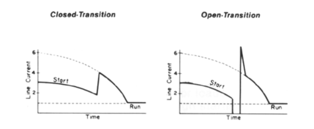
Figure 4: Open Transition Vs. Closed Transition Starters
This is because the motor acts as a generator for a few cycles after power is removed, until the residual voltage decays. When the motor is reconnected to the power source the effect is the same as connecting two generators out-of-phaseÑhigh inrush current. Closed transition starters do reduce the maximum voltage dip, but the amount of reduction depends on the speed of the motor at the time of transition. To keep the voltage dip to a minimum, it is important to allow as much time for the motor to accelerate as possible before making the transition. The starters usually have an adjustable time delay for this purpose.
Some Types of Reduced Voltage Starters Primary Resistor Starting
In this type of starter, resistors are connected in the motor lines to produce a voltage drop due to the motor starting current. A timing relay is connected to short out the resistors after motor acceleration. The motor starts at reduced voltage and operates at full voltage. These starters provide very smooth starting due to increasing voltage across the motor terminals as the motor accelerates. Since motor current decreases as speed increases, the voltage drop
across the resistor is less as the motor approaches rated speed. When the resistor is shorted out when the motor is nearly at rated speed, there is little increase in current or torque.
Standard primary resistor starters provide one step of resistance with about 70% of line voltage at the motor terminals at the time the starting contacts close. Line current is also reduced to about 70% of rated locked rotor current and about 49% of rated locked rotor torque is available.
Maximum inrush KVA is also limited to about 50% of the motor’s rated locked rotor KVA. Because this type of starter increases the power factor of the motor starting load, we find that it frequently overloads the engine on the generator set. We recommend that resistance starters not be used on generator sets.
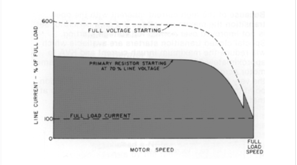
Figure 5: Primary Resistor Starting
Primary Reactor Starting
This type of starter uses reactors connected in the motor lines to reduce starting power requirements. These starters provide a low power factor load, but must be designed to match the characteristics of the particular motor being started.
Primary reactor starters reduce the starting KVA load by 35-50% and reduce the starting torque available from the motor by 60-75%. When properly applied, these starters work well with generator sets.
Wye-Delta Starting
Some motors have 6 leads which allow them to be connected in either wye or delta. When wye connected, the motor has a voltage rating 173% of its delta voltage rating. By connecting the motor windings in the wye configuration and using a voltage source corresponding to the delta rating, starting current and torque are reduced. The starter is not truly a reduced voltage type, but the effect is the same. Wye-delta starters are usually open transition type. On the initial start, two contactors close: one to connect the windings in wye and one to energize them. After a time delay the wye contactor opens and a third contactor closes to reconnect the motor in delta. With the motor connected in wye, both starting torque and current are 33% of the delta connection values.
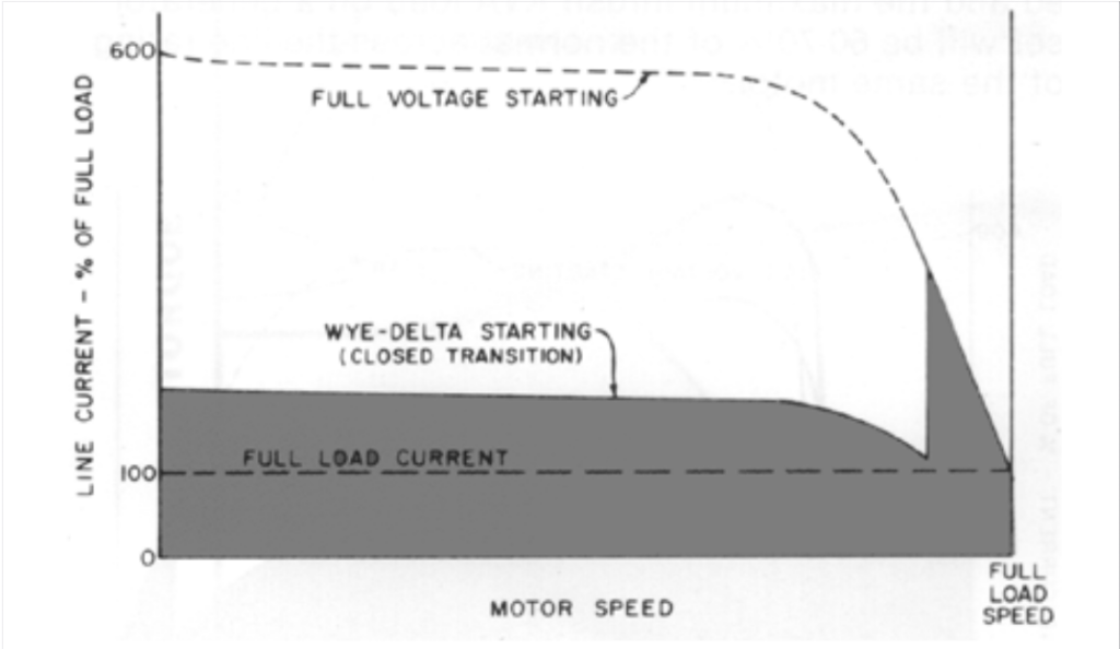
Figure 6: Wye-Delta Starting
Because of the high current inherent with open transition the maximum voltage dip on a generator set is not improved over normal full voltage starting. Special closed transition starters are available which will reduce the maximum inrush current and KVA to approximately 60% of the maximum starting the same motor across-the-line, delta connected. Because of the very low starting torque, the time to transition point must be relatively long to avoid high currents at that point.
Part Winding Starting
Part Winding starters are used with motors having two identical windings intended to be connected in parallel. These windings can be energized in sequence to provide reduced starting current and torque. When one winding is energized, the torque is about 50% of “both winding” rating, and line current is 60-70%, depending on motor design. Part winding starters are not truly reduced voltage starters, but the effect is similar. Since they are inherently closed transition, the maximum inrush current occurs at the moment the first winding is energized and the maximum inrush KVA load on a generator set will be 60-70% of the normal across-the-line rating of the same motor.
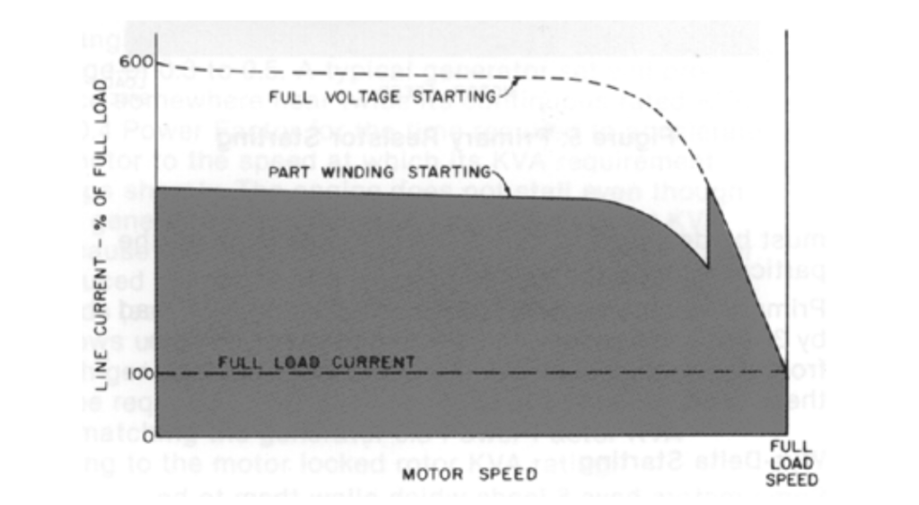
Figure 7: Part Winding Starting
Autotransformer Starting
This type of starter generally gives the best results with generator sets. The starter provides reduced voltage at the motor terminals from a tapped 3-phase auto-transformer. Taps on the transformer provide selection of 80, 65 or 50 percent of line voltage to the motor terminals initially. Starting torque is reduced to 64%, 42% or 25% of the full voltage but because of transformer action line current and KVA are reduced in the same amounts depending on the transformer tap selected.
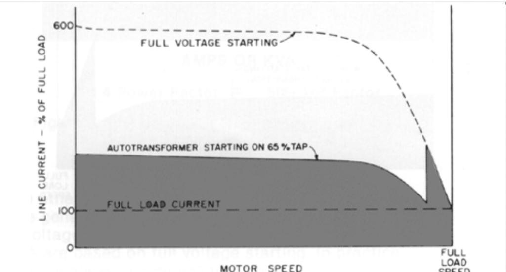
Figure 8: Autotransformer Starting
Summary Table 3 shows the various types of reduced voltage starters and summarizes their relative advantages and disadvantages. Figure 9 shows the inrush current characteristics of the various types of starters on a single graph for comparison.
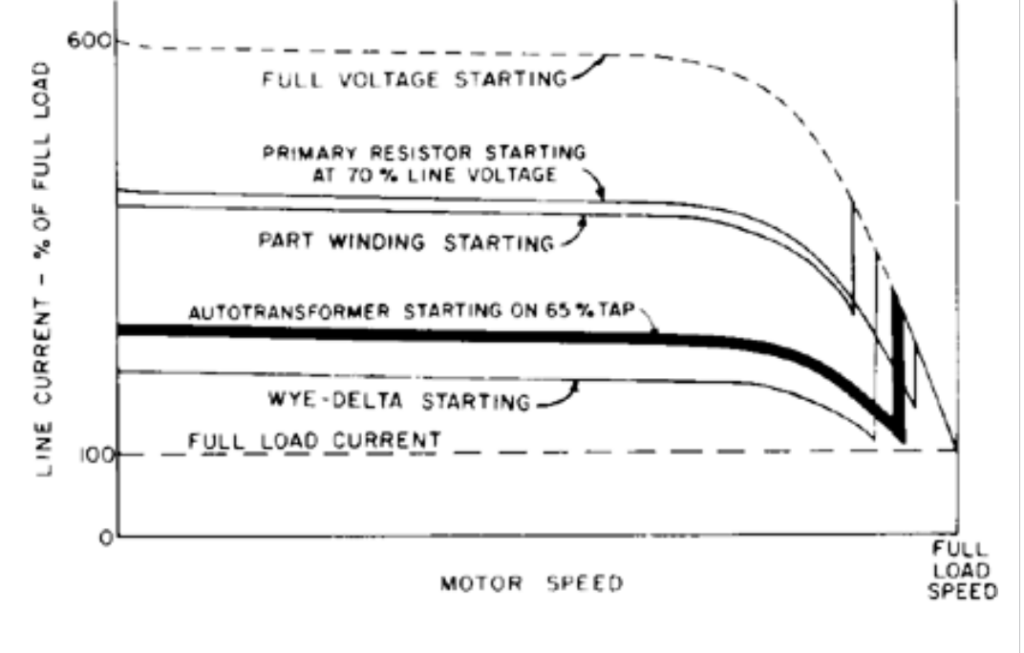
Figure 9: Part Winding, Wye-Delta, Primary Resistor or Autotransformer Starting
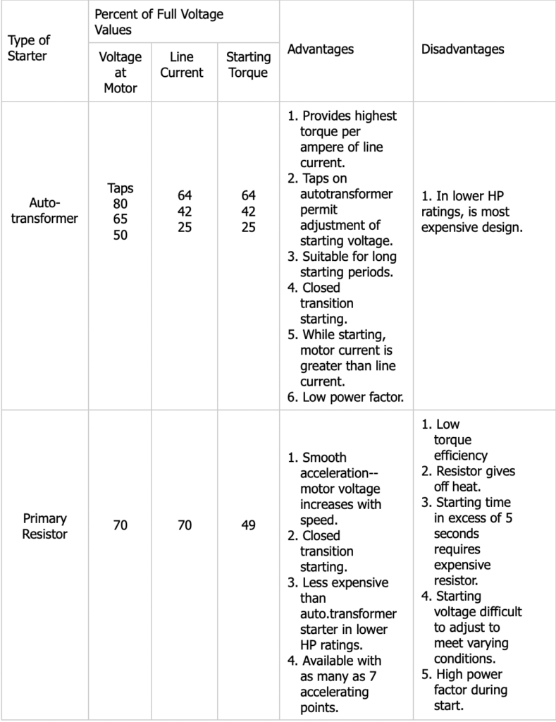
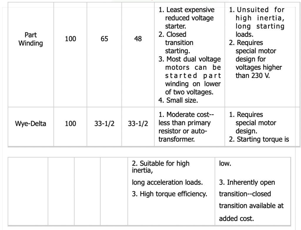
Table 3: Reduced Voltage Starters Application Data
Because there will still be some voltage dip when the motor is started on a generator set, and that dip further reduces available torque, it usually is not practical to use the 50% tap with a generator set. Closed transition type autotransformer reduced voltage starters can be helpful when starting large motors on generator sets.
We have had experience with a variety of other special applications and are glad to provide assistance with whatever motor starting problems you may encounter.